Induction coil selection: workpiece geometry, frequency and power
A practical review of workpiece shape, heating zone, frequency, power and coil clearance when selecting an induction-heating process.
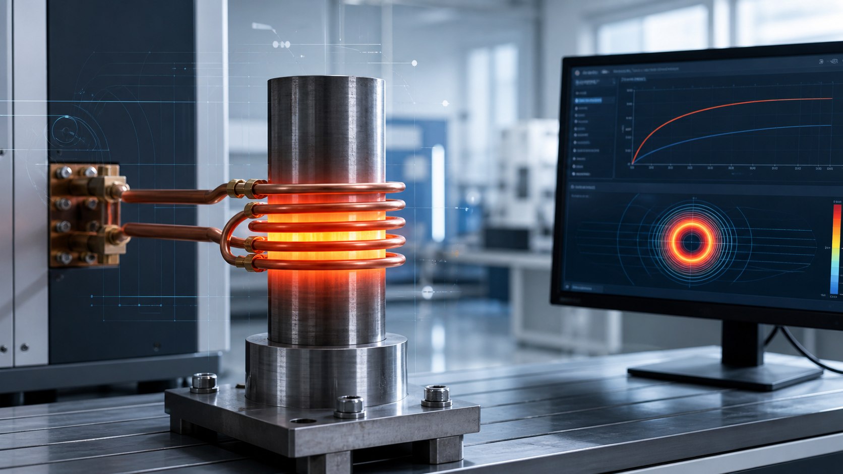
An induction coil should not be chosen from the power-supply rating alone. Workpiece shape, the intended heating zone, material condition and production cycle all affect the process window. Start by defining the target temperature, acceptable variation and quality checks. Start with geometry Bars, tubes, plates and localized features require different coil arrangements. Coil-to-part clearance, coil length and workpiece motion affect coupling and heating uniformity. Overall heating and local surface treatment should use appropriate measurement locations rather than relying on one temperature reading. Consider frequency and power together Frequency influences current distribution in the workpiece; power and heating time govern energy input. Electrical resistance and magnetic behavior may change with temperature, so room-temperature properties should not be treated as constant throughout the cycle. Review supply capacity and coil cooling at the same time. Validate with measured results Record geometry, material batch, clearance, frequency, power, heating time and temperatures at relevant positions. Safety-critical or complex parts require measured temperature histories and, where applicable, metallographic and hardness checks. For a specific application, contact the IFcores engineering team .